Author: mikronetpk

Exchange Server 2010 Installation & Configuration

In this post I’m going to demonstrate how to install Exchange 2010 SP1 and how to configure it to receive and send emails to the external world.

First step is to click HERE and install all prerequisites.

Now let’s start the installation.

Run the Exchange setup, click on Step3: Choose Exchange language option and click on Install only languages from the DVD.

Click on Step 4: Install Microsoft Exchange.


Click on Next.


Accept the license agreement and click on Next.


Select whether you want to enable the Error Reporting feature. Click on Next.


Select the type of install you want to perform. In our case we are going to perform the Typical Exchange Server Install which will install the Hub Transport, Client Access, Mailbox and Exchange Management Tools. Make sure you also select Automatically install Windows Server roles and features required for Exchange Server. Click on Next.


Specify the name of your organization. If different people manage AD and Exchange then select Apply Active Directory split permissions security model to the Exchange organization, otherwise leave it unticked. Click on Next.


If you have computers running Outlook 2003 select Yes otherwise select No. Click on Next.


Now specify the domain name that external clients will use to connect to Exchange. Click on Next.


Select whether or not you want to join the Customer Experience Improvement Program. Click on Next.


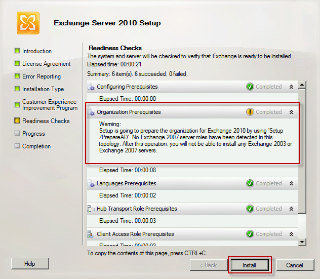
Make sure the user you are performing the installation is member of the Schema Admins and Enterprise Admins groups otherwise you will receive the message below.


Note that Exchange setup will automatically make all required changes to AD.
e.g. extend AD schema
Click on Next.


If everything worked as expected you should see a screen like the one below. Select Finalize the installation using the Exchange Management Console. Click on Finish.


Once the installation is finished you will receive a message to restart the server. You can do it now or do it later. Just make sure you do it before placing it into production.


Install all updates available.


Now let’s configure it to receive and send emails to the internet. In the Exchange Management Console, expand Microsoft Exchange On-Premises, expand Organization Configuration and select Hub Transport. In the Actions pane click on New Send Connector.


Give it a name and select Internet as the Send connector. Click on Next.


Click on Add and type * in the Address space field. Click on OK. Click on Next.


Select Use domain name system (DNS) “MX” records to route mail automatically and tick Use the External DNS Lookup settings on the transport server. Click on Next.


Click on Add. Select your Exchange server. Click on OK. Click on Next.


Click on New.


Click on Finish.


In the Server Configuration Node select Default SERVERNAME and click on Properties.


In the Permission Groups tab make sure you select Anonymous users, Exchange users, Exchange servers and Legacy Exchange Server. Click on OK.


Now that the Exchange configuration is completed go to your DNS server and make sure you have an A record with the name you specified earlier during the Exchange installation and your external clients will use to connect to your Exchange server. Make sure you also have a Reverse Lookup Zone configured.


In your provider hosting your public DNS records make sure you have an MX record with the same name you have just specified in your internal DNS for external clients.


Unequal 2 WAN Load balancing pcc with hotspot

2wan_pic
Change setting with your local network

/ip address
add address=192.168.2.2/24 interface=WAN1
add address=192.168.0.2/24 interface=WAN2
add address=192.168.5.1/24 interface=Local

/ip dns
set allow-remote-requests=yes cache-size=5000KiB max-udp-packet-size=2048 servers=8.8.8.8,8.8.4.4

/ip firewall mangle
add chain=input in-interface=WAN1 action=mark-connection new-connection-mark=WAN1_conn
add chain=input in-interface=WAN2 action=mark-connection new-connection-mark=WAN2_conn
add action=mark-routing chain=output connection-mark=WAN1_conn new-routing-mark=to_WAN1
add action=mark-routing chain=output connection-mark=WAN2_conn new-routing-mark=to_WAN2
add chain=prerouting dst-address=192.168.2.0/24 in-interface=Local
add chain=prerouting dst-address=192.168.0.0/24 in-interface=Local
add action=mark-connection chain=prerouting dst-address-type=!local hotspot=auth in-interface=Local new-connection-mark=WAN1_conn per-connection-classifier=both-addresses-and-ports:2/0
add action=mark-connection chain=prerouting dst-address-type=!local hotspot=auth in-interface=Local new-connection-mark=WAN2_conn per-connection-classifier=both-addresses-and-ports:2/1
add action=mark-connection chain=prerouting dst-address-type=!local hotspot=auth in-interface=Local new-connection-mark=WAN1_conn per-connection-classifier=both-addresses-and-ports:2/2
add action=mark-routing chain=prerouting connection-mark=WAN1_conn in-interface=Local new-routing-mark=to_WAN1
add action=mark-routing chain=prerouting connection-mark=WAN2_conn in-interface=Local new-routing-mark=to_WAN2

/ip firewall nat
add action=masquerade chain=srcnat out-interface=WAN1
add action=masquerade chain=srcnat out-interface=WAN2

/ip route
add check-gateway=ping distance=1 gateway=192.168.2.1 routing-mark=to_WAN1
add check-gateway=ping distance=1 gateway=192.168.0.1 routing-mark=to_WAN2
add check-gateway=ping distance=1 gateway=192.168.2.1
add check-gateway=ping distance=2 gateway=192.168.0.1

Source:- http://www.virtualitsupport.com

Public vs Private Cloud?

As businesses look to adopt Cloud Services, they have quite different approaches available to them based on what’s been termed Public Cloud and Private Cloud.

Services delivered over the public Internet by providers, and accessed by users via web applications, are often referred to as Public Cloud. This includes Microsoft, Google, Amazon and Salesforce.com.

Private Cloud enables customers to benefit from the same characteristics of Cloud Services, including virtualisation and shared hardware costs, but delivered via a private network from the closed infrastructure of an external provider.

Businesses are reviewing these different approaches and deciding which route to take. In many cases the Hybrid approach is followed, whereby some applications are delivered using Public Cloud services, such as Microsoft Office 365, whereas more business specific applications, such as an internally developed CRM system, might be delivered via Private Cloud.

For MDNX, Cloud Services are about the virtualisation of specific internal business applications and delivering them from multiple data centres for resilience.

For many businesses, moving key IT applications into a Public Cloud is too much of a risk. The Private Cloud approach allows us to be much more transparent on where the applications and databases reside, and how these are secured – both in terms of the computing platform and the network.

The move to Cloud Services may be gradual, perhaps starting with less critical applications first. However it has become increasingly clear that the delivery of applications back into the business is highly dependent on the performance and security of the network. Rather than using the Internet where quality of service cannot be controlled and additional layers of security must be built, using an MPLS-based network provides a much better solution. With an MPLS VPN our Carrier Integration approach enables us to deliver a best fit solution to our customers in terms of performance, resilience, and costs along with meaningful SLAs.

What is Cloud?

There is much confusion about the definition of Cloud Services. From an enterprise perspective it means being able to access secure, scalable computing resources (processing, memory, storage, and applications) from a shared infrastructure, delivered over a public or private network. Importantly the enterprise does not need to have knowledge of, or responsibility for, the equipment used to deliver services.

As such a key technology that is fundamental to the delivery of Cloud Services is Virtualisation. Hardware virtualisation refers to the creation of a virtual machine that acts like a real computer with an operating system. Software executed on these virtual machines is separated from the underlying hardware resources. The major advantage of this approach is that computing resources can be more closely aligned to the needs of the application, resulting in more efficient use of resources and ultimately reduced costs.

The Cloud is often thought of as the public Internet, however for many enterprises Virtual Private Cloud services are more relevant as these are delivered from the closed infrastructure of a provider and delivered via a secure private network.

What’s driving demand?
A number of factors have been driving the shift from in-house computing and dedicated hosting to Cloud Services:

1. Hardware is massively under-utilised
Many businesses have built up a number of servers that are used for different applications and databases. These may also be spread around different offices and data centres. The reality today is that machines only run at 10 or 15% of total processing capacity, and these lightly loaded servers still take up valuable space and draw increasingly expensive power.
There must be a better way to match computing capacity with load to overcome gross inefficiency. Virtualisation enables this by having a single platform that is able to seamlessly support multiple systems, raising utilisation rates and providing a simple way of supporting growth.

2. Availability and cost of data centre space is a growing problem
The growth in the use of IT and the Internet to support business processes has meant a vast number of servers have been put into use. These take up space and power and this has led to an on-going issue of available data centre space and power. A virtualised, cloud service removes the need to keep finding more space. The increasing cost of power is also a key factor in escalating operating costs. By reducing the number of physical servers a company can directly reduce the costs of both space and power.

3. System administration costs continue to rise
The greater the number of systems and the more dispersed they are across locations, the higher the staff costs are for running and maintaining them. Cloud Services reduce the number of servers and therefore directly reduce the staff costs related to administering them.

4. Storage demands mount
Data is becoming increasingly critical in the running of a business. Data is used in real time for key business applications and for back-up to ensure the business can continue to operate. It is also used for archiving purposes, for example for legal reasons. The demand for secure, scalable and cost effective storage is increasing. Rather than trying to build this capability in-house, storage is an ideal fit for the cloud model by providing access to large scale, economic and resilient infrastructure.

The benefits of Cloud Services
• Lower Total Cost of Ownership
Studies have shown that through the computing efficiency virtualisation delivers, IT operating costs can be reduced by up to 50% (through a reduction in server, space, power, and staff costs). The need for on-going capital expenditure is removed, particularly for technology refresh, with costs transferring to more predictable operating costs.

• Reliability
Cloud solutions deliver high levels of resilience, whether through resource sharing within a single virtual platform or enabling high availability services across geographically dispersed systems.

• Flexibility and Scalability
As a business changes it can scale the amount of computing and storage capacity required in much shorter timeframes than would be required to implement new servers.
This flexibility is ideal for IT staff that want to develop and test new applications without having to purchase and install new hardware.

• Predictable Pricing
The business will benefit from a managed service with known charges, and more granular costs of scaling.

• IT Staff can focus on Core Activities
Rather than staff spending their time keeping the servers running, they can focus on more business critical activities such as implementing new applications.

• Less Risk
The scale that cloud infrastructure enables allows business applications to be run in a more secure and resilient environment than could be created in-house unless substantial investment is made.

IP addressing – a numbers game
The depletion of the IPv4 allocation pool has been a concern since the late 1980’s, when the internet really started to see enormous growth. Since then there have been many techniques developed to address the IPv4 scalability issues (limited to 4.3 billion addresses) such as CIDR, NAT and finally the introduction of IPv6 in 1998.

IPv6 is the only workable solution to IPv4 depletion as it can provide 340 undecillion (3.4×1038) addresses. This therefore eliminates the need for NAT in the future internet. To put the numbers in perspective, if the current pool of IPv4’s 4.3 billion addresses were the size of a golf ball, the new IPv6’s 340 undecillion address space would be about the size of the sun.

IPv4 to IPv6 – The network problem 
IPv4 and IPv6 are completely separate Network layer protocols that cannot interact directly. As the internet community rolls out IPv6, what is actually happening is the build out of a second, logical IPv6 internet, which runs in parallel and over the same physical Layer1 &2 infrastructure as the current IPv4 internet, with the eventual goal of phasing out the IPv4 Internet.

Since there is no set time limit when everything must be IPv6 network providers need to design and implement mechanisms that allow networks to work on IPv4 and IPv6 at the same time, and also, in preparation for the eventual date when IPv4 address space is completely exhausted, have a solution where they can deploy IPv6 only sites that can still communicate with the IPv4 Internet.

IPv4 to IPv6 – the solutions
Dual-Stack
Dual stack means that all devices are able to run both IPv4 and IPv6 in parallel. This is the solution that should be implemented now as it offers flexibility and coexistence, allowing users to reach both IPv4 and IPv6 simultaneously.

Dual stack does not require any tunnelling over networks as IPv4 and IPv6 work independently of each other. This allows for a granular migration of services from IPv4 to IPv6 over time.

Dual-Stack Lite

Dual Stack Lite is a solution which is primarily adopted for broadband solutions. Its design does not require any registered IPv4 address space to be assigned to a Customer site. In this design only IPv4 private addresses for the LAN clients are used and IPv4 in encapsulated in IPv6 over the WAN.

The network provider implements a Carrier Grade NAT (CGN) device within its network infrastructure and the Dual Stack Lite CPE uses its unique IPv6 connection to deliver packets to the CGN which has a pool of IPv4 addresses.

mdnx

Subnetting-3

One important thing we should notice is that a valid subnet mask must have all bit “1″s and “0″s successive, in which bit “1″s must be on the left; bit “0″s must be on the right. Therefore we only have 8 situations:

Subnet_Decimal_Binary.jpg
Table 2 – lists all valid subnet masks

This is a very important table to do subnet quickly! Please take some time to learn it by heart. Make sure you remember the right-most bit “1″ position (the least significant bit 1, which are in red in the above table) and their equivalent decimal values.

In most cases, this table is used to quickly convert a number from decimal to binary value without any calculation. For example, you can quickly convert the 4th octet of the subnet mask 255.255.255.248 to 11111000. Or if you are given a subnet of /29 you will know it equals to 255.255.255.248 (by thinking “/24 is the default subnet mask of class C so /29 will have the right-most bit “1″ at 5th position).

Try to practice with these questions:

+ “/28″ in binary form?
+ “255.255.224.0″ in binary form?
+ “255.192.0.0″ in slash notation form?
+ “/26″ in binary form?
+ “255.128.0.0″ in binary form?
+ “248.0.0.0″ in slash notation form?

(Please try to solve by yourself before reading the solution)

Answers:

+ /28 -> 1111 1111.1111 1111.1111 1111.1111 0000
+ 255.255.224.0 -> 1111 1111.1111 1111.1110 0000.0000 0000
+ 255.192.0.0 -> /10
+ /26 -> 1111 1111.1111 1111.1111 1111.1100 0000
+ 255.128.0.0 -> 1111 1111.1000 0000.0000 0000.0000 0000
+ 248.0.0.0 -> /5

How to find out the increment number?

The increment is the heart of subnetting; if you can find out the increment, you can find all the information to solve a subnetting question. So it is usually the first thing you must find out in a subnetting question.

The increment number is the number specifying how “big” your subnets are. Let’s take an example of the increment number! Did you remember the subnets in “Exercise 3″ in the previous part? By changing bits in the Network part, we found out 4 subnets:

+ First subnet: 198.23.16.0/30 (the 4th octet is 00000000)
+ Second subnet: 198.23.16.4/30 (the 4th octet is 00000100)
+ Third subnet: 198.23.16.8/30 (the 4th octet is 00001000)
+ Fourth subnet: 198.23.16.12/30 (the 4th octet is 00001100)

In this case the increment is 4 (in the 4th octet) because the “difference” between two successive subnets is 4 (from 0 -> 4; from 4 -> 8; from 8 -> 12)

There are 2 popular ways to find out the increment number:

1) Use the formula:

Increment = 256 – x

In which “x” is the first octet (counting from the left) which is smaller than 255 in a subnet mask. For example:

+ In a subnet mask of 255.224.0.0 -> x = 224
+ In a subnet mask of /29 -> x = 248 (because /29 = 255.255.255.248)
+ In a subnet mask of 1111 1111.1111 1100.0000 0000.0000 0000 -> x = 252

In the case you see a subnet mask of 255.255.255.255 (which is very rare in CCNA), x = 255

Note: Also remember which octet “x” belongs to because we have to plus the increment to that octet.

Now let’s solve Exercise 3 again by using this formula:

Exercise 3 one again (with the formula 256 – x):

Your company has just been assigned the network 198.23.16.0/28. How many subnets and hosts-per-subnet you can create with a subnet mask of 255.255.255.252?

The subnet mask is 255.255.255.252 -> x = 252 (x belongs to 4th octet)

Therefore the Increment = 256 – 252 = 4

The initial network 198.23.16.0/28 is also the first subnet, so:
+ The first subnet: 198.23.16.0/30
+ The second subnet: 198.23.16.4/30 because the increment is 4 so we plus the network address with it to get the next network address (0 + 4 = 4)
+ The third subnet: 198.23.16.8/30 (4 + 4 = 8)
+ The fourth subnet: 198.23.16.12/30 (8 + 4 = 12)

Note: We know there are only 4 subnets because we borrow 2 bits.

2) Learn by heart the decimal value of the rightmost bit “1″ in the subnet mask:

Another way to find the increment value is to write “x” in binary: 11110000. Consider the rightmost bit “1″, the decimal value of this bit is the increment value. In this case it equals to 16.

The table below summarizes the decimal values of bit “1″ depending on its position. To use this method, you should learn by heart this table:

Subnet_bit_1_significance.jpg

Table 3 – How to find out increment based on the “least-significant” (rightmost) bit 1

Now let’s solve Exercise 3 again by using this method:

Exercise 3 one again (with the “decimal value of the rightmost bit 1″ method):

Your company has just been assigned the network 198.23.16.0/28. How many subnets and hosts-per-subnet you can create with a subnet mask of 255.255.255.252?

First use Table 2 to convert 252 to 1111 1100. The decimal value of the rightmost bit “1″ is 4 (according to Table 3) -> The Increment is 4.

After finding out the increment we can deduce 4 subnets it creates.

The initial network 198.23.16.0/28 is also the first subnet, so:
+ The first subnet: 198.23.16.0/30
+ The second subnet: 198.23.16.4/30 because the increment is 4 so we plus the network address with it to get the next network address (0 + 4 = 4)
+ The third subnet: 198.23.16.8/30 (4 + 4 = 8)
+ The fourth subnet: 198.23.16.12/30 (8 + 4 = 12)

Note: We should only choose one method to use and try to practice, practice & practice more with it. Practice until you can solve any subnetting questions within 20 seconds!

Maybe you will ask why 256 can help you find the increment. In fact, by using the formula Increment = 256 – x you are trying to separate the rightmost bit “1″ from other bits:

256 – x = 255 – x + 1

In which “255 – x” will convert all bit “0″s to bit “1″s and all bit “1″s to “0″s while “+1″ part will make our result have only one bit “1″ left. For example, if x = 240 then:

Why_256_magic.jpg

So in fact we can say two above methods are the same!

Resource:-         http://www.9tut.com/

Subnetting-2

Calculate how many networks and hosts-per-subnet


In our example, you may raise a question: “when we borrow 8 bits, how many sub-networks and how many hosts per sub-network do it create?”

Note: From now, we will call sub-networks “subnets”. This term is very popular so you should be familiar with it.

How many new subnets?

Because we can change any bit in the second octet to create a new subnet, each bit can be “0″ or “1″ so with this subnet mask (255.255.0.0) we can create 28 more subnets. From here we can deduce the formula to calculate the newly created subnets. Suppose n is the number of bits we borrow:

The number of newly created subnets = 2n

In our example, we borrow 8 bits so we will have 2n = 28 = 256 subnets!

How many hosts per subnet?

The number of hosts per subnet is depended on the Host part, which is indicated by the “0″ part of the subnet mask. So suppose k is the number of bits “0″ in the subnet mask. The formula to calculate the number of hosts is 2k. But notice that with each subnet, there are two addresses we can’t assign for hosts because they are used for network address & broadcast address. Thus we must subtract the result to 2. Therefore the formula should be:

The number of hosts per subnet = 2k – 2

In our example, the number of bit “0″ in the subnet mask 255.255.0.0 (in binary form) is 16 so we will have 2k – 2 = 216 – 2 = 65534 hosts-per-subnet!

Some other examples

Well, practice makes perfect so we should have some more exercises to be familiar with them. But remember that this is only the beginning in your journey to become a subnetting guru 🙂

Exercise 1

Your company has just been assigned the network 4.0.0.0. How many subnets and hosts-per-subnet you can create with a subnet mask of 255.255.255.0?

(Please try to solve by yourself before reading the solution ^^)

Solution

First of all you have to specify which class this network belongs to. According to Table 1, it belongs to class A (simply, class A ranges from 1 to 126) and its default subnet mask is 255.0.0.0. Therefore if we use a subnet mask of 255.255.255.0, it means we borrowed 16 bits (to convert from 0 to 1).

255.0.0.0 = 1111 1111.0000 0000.0000 0000.0000 0000
255.255.255.0 = 1111 1111.1111 1111.1111 1111.0000 0000

Now use our above formulas to find the answers:

The number of newly created subnets = 216 = 65536 (with 16 is the borrowed bits)
The number of hosts per subnet = 28 – 2 = 254 (with 8 is the bit “0″s left in the 255.255.255.0 subnet mask)

Exercise 2

Your company has just been assigned the network 130.0.0.0. How many subnets and hosts-per-subnet you can create with a subnet mask of 255.255.128.0?

(Please try to solve by yourself before reading the solution ^^)

Solution

130.0.0.0 belongs to class B with the default subnet mask of 255.255.0.0. But is the subnet mask of 255.255.128.0 strange? Ok, let’s write all subnet masks in binary:

255.255.128.0 = 1111 1111.1111 1111.1000 0000.0000 0000

This is a valid subnet because all bit “1″s and “0″s are successive. Comparing to the default subnet mask, we borrowed only 1 bit:

255.255.0.0 = 1111 1111.1111 1111.0000 0000.0000 0000

Therefore:

The number of newly created subnets = 21 = 2 (with 1 is the borrowed bits)
The number of hosts per subnet = 215 – 2 = 32766 (with 15 is the bit “0″s left in the 255.255.128.0 subnet mask)


Exercise 3

Your company has just been assigned the network 198.23.16.0/28. How many subnets and hosts-per-subnet you can create with a subnet mask of 255.255.255.252?

(Please try to solve by yourself before reading the solution ^^)

Solution

In this exercise, your company was given a “subnetted” network from the beginning and it is not using the default subnet mask. So we will compare two subnet masks above:

/28 = 1111 1111.1111 1111.1111 1111.1111 0000 (=255.255.255.240)
255.255.255.252 = 1111 1111.1111 1111.1111 1111.1111 1100 (= /30)

In this case we borrowed 2 bits. Therefore:

The number of newly created subnets = 22 = 4 (with 2 is the borrowed bits)
The number of hosts per subnet = 22 – 2 = 2 (with 2 is the bit “0″s left in the 255.255.255.252 subnet mask)

In this exercise I want to go a bit deeper into the subnets created. We learned there are 4 created subnets but what are they? To find out, we should write all things in binary:

Class_C_binary_form.jpg

Because two subnet masks (/28 & /30) only affect the 4th octet so we don’t care about the first three octets. In the 4th octet we are allowed to change 2 bits (in the green box) of the IP address to create a new subnet. So there are 4 values we can use: 00, 01, 10 & 11. After changing, we convert them back to decimal numbers. We get 4 subnets:

+ First subnet: 198.23.16.0/30 (the 4th octet is 00000000)
+ Second subnet: 198.23.16.4/30 (the 4th octet is 00000100)
+ Third subnet: 198.23.16.8/30 (the 4th octet is 00001000)
+ Fourth subnet: 198.23.16.12/30 (the 4th octet is 00001100)

So how about hosts per subnet? Please notice that all these 4 subnets are successive. So we can deduce the range of these subnets:

+ First subnet: ranges from 198.23.16.0 to 198.23.16.3
+ Second subnet: ranges from 198.23.16.4 to 198.23.16.7
+ Third subnet: ranges from 198.23.16.8 to 198.23.16.11
+ Fourth subnet: ranges from 198.23.16.12 to 198.23.16.15

Let’s analyze the first subnet which ranges from 198.23.16.0 to 198.23.16.3. Notice that all networks (and subnets) have a network address and a broadcast address. In this case, the network address is 198.23.16.0 and the broadcast address is 198.23.16.3 and they are not assignable or usable for hosts. This is the reason why we have to subtract 2 in the formula “The number of hosts per subnet = 2k – 2″. After eliminating these 2 addresses we have 2 addresses left (which are 198.23.16.1 & 198.23.16.2) as calculated above.

Subnettting -1

The table below summarizes the possible network numbers, the total number of each type, and the number of hosts in each Class A, B, and C network.

Default subnet mask Range
Class A 255.0.0.0 (/8) 1.0.0.0 – 126.255.255.255
Class B 255.255.0.0 (/16) 128.0.0.0 – 191.255.255.255
Class C 255.255.255.0 (/24) 192.0.0.0 – 223.255.255.255

Table 1 – Default subnet mask & range of each class

Class A addresses begin with a 0 bit. Therefore, all addresses from 1.0.0.0 to 126.255.255.255 belong to class A (1=0000 0001; 126 = 0111 1110).
The 0.0.0.0 address is reserved for default routing and the 127.0.0.0 address is reserved for loopback testing so they don’t belong to any class.
Class B addresses begin with a 1 bit and a 0 bit. Therefore, all addresses from 128.0.0.0 to 191.255.255.255 belong to class B (128=1000 0000; 191 = 1011 1111).
Class C addresses begin with two 1 bits and a 0 bit. Class C addresses range from 192.0.0.0 to 223.255.255.255 (192 = 1100 0000; 223 = 1101 1111).

Class D & E are used for Multicast and Research purposes and we are not allowed to subnet them so they are not mentioned here.

Note: The number behind the slash notation (/) specifies how many bits are turned on (bit 1). For example:

+ “/8″ equals “1111 1111.0000 0000.0000 0000.0000 0000″ -> 8 bits are turned on (bit 1)
+ “/12″ equals “1111 1111.1111 0000.0000 0000.0000 0000″ -> 12 bits are turned on (bit 1)
+ “/28″ equals “1111 1111.1111 1111.1111 1111.1111 0000″ -> 28 bits are turned on (bit 1)
+ “/32″ equals “1111 1111.1111 1111.1111 1111.1111 1111″ -> 32 bits are turned on (bit 1) and this is also the maximum value because all bits are turned on.

The slash notation (following with a number) is equivalent to a subnet mask. If you know the slash notation you can figure out the subnet mask and vice versa. For example, “/8″ is equivalent to “255.0.0.0″; “/12″ is equivalent to “255.240.0.0″; “/28″ is equivalent to “255.255.255.240″; “/32″ is equivalent to “255.255.255.255″.

Class_A_B_C_network_host_portions.jpg

The Network & Host parts of each class by default

From the “default subnet mask” shown above, we can identify the network and host part of each class. Notice that in the subnet mask, bit 1 represents for Network part while bit 0 presents for Host part (255 equals to 1111 1111 and 0 equals to 0000 0000 in binary form).


What is “subnetting”?

When changing a number in the Network part of an IP address we will be in a different network from the previous address. For example, the IP address 11.0.0.1 belongs to class A and has a default subnet mask of 255.0.0.0; if we change the number in the first octet (a block of 8 bits, the first octet is the leftmost 8 bits) we will create a different network. For example, 12.0.0.1 is in a different network from 11.0.0.1. But if we change a number in the Host part, we are still in the same Network. For example, 11.1.0.1 is in the same network of 11.0.0.1.

The problem here is if we want to create 300 networks how can we do that? In the above example, we can only create different networks when changing the first octet so we can create a maximum of 255 networks because the first octet can only range from 1 to 255 (in fact it is much smaller because class A only range from 1 to 126). Now we have to use a technique called “subnetting” to achieve our purpose.

“Subnetting” means we borrow some bits from the Host part to add to the Network part. This allows us to have more networks than using the default subnet mask. For example, we can borrow some bits in the next octet to make the address 11.1.0.1 belong to a different network from 11.0.0.1.

How to subnet?

Do you remember that I said “in the subnet mask, bit 1 represents for Network part while bit 0 presents for Host part”? Well, this also means that we can specify how many bits we want to borrow by changing how many bit 0 to bit 1 in the subnet mask.


Let’s come back to our example with the IP 11.0.0.1, we will write all numbers in binary form to reveal what a computer really sees in an IP address.

Class_A_binary_form.jpg

Now you can clearly see that the subnet mask will decide which is the Network part, which is the Host part. By borrowing 8 bits, our subnet mask will be like this:

Class_A_subnet_binary_form.jpg

After changing the second octet of the subnet mask from all “0″ to all “1″, the Network part is now extended. Now we can create new networks by changing number in the first or second octet. This greatly increases the number of networks we can create. With this new subnet mask, IP 11.1.0.1 is in different network from IP 11.0.0.1 because “1″ in the second octet now belongs to the Network part.

So, in conclusion we “subnet” by borrowing bit “0″ in the Host portion and converting them to bit “1″. The number of borrowed bits is depended on how many networks we need.

Note: A rule of borrowing bits is we can only borrow bit 0 from the left to the right without skipping any bit 0. For example, you can borrow like this: “1111 1111. 1100 0000.0000 0000.0000 0000″ but not this: “1111 1111. 1010 0000.0000 0000.0000 0000″. In general, just make sure all your bit “1″s are successive on the left and all your bit “0″s are successive on the right.

Refer to the exhibit. An administrator pings the default gateway at 10.10.10.1 and sees the output as shown. At which OSI layer is the problem?

C:\> ping 10.10.10.1
Pinging 10.10.10.1 with 32 bytes of data:
Request timed out.
Request timed out.
Request timed out.
Request timed out.
Ping statistics for 10.10.10.1:
Packets: sent – 4, Received = 0, Lost – 4 (100% loss)

A. data link layer
B. application layer
C. access layer
D. session layer
E. network layer

Answer: E

Explanation

The Network layer is responsible for network addressing and routing through the internetwork. So a ping fails, you may have an issue with the Network layer (although lower layers like Data Link & Physical may cause the problem).


Before installing a new, upgraded version of the IOS, what should be checked on the router, and which command should be used to gather this information? (Choose two)

A. the amount of available ROM
B. the amount of available flash and RAM memory
C. the version of the bootstrap software present on the router
D. show version
E. show processes
F. show running-config

Answer: B D

Explanation

When upgrading new version of the IOS we need to copy the IOS to the Flash so first we have to check if the Flash has enough memory or not. Also running the new IOS may require more RAM than the older one so we should check the available RAM too. We can check both with the “show version” command.